Shenzhen Tengxingsheng Electronics Co., Ltd.
Contact: Miss Wen
Tel: 0755-23286182
Mob: 13570819121
QQ: 1456258664
QQ: 2316907424
Fax: 0755-23286183
Email: txspcbsc@163.com txspcb@163.com
Web : en.txspcb.cn
Add: 3rd Floor, Building 3, Jinkang Industrial Park, No. 1 Shajing Road, Baoan District, Shenzhen
How are the circuit boards connected?
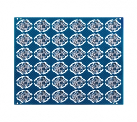
Double-sided circuit board
Electronic equipment must be interconnected according to the circuit schematic diagram to achieve the predetermined function. If the connection is wrong, the entire circuit board will be invalid. Therefore, choosing the connection with the best combination of reliability, manufacturability and economy is one of the important contents of circuit board design. one. There are many kinds of external connection methods, which should be flexibly selected according to different characteristics. The following two methods are the most common.
Welding method
The advantages of this method are simple operation, low cost and high reliability, which can avoid failures caused by poor contact; the disadvantage is that the exchange and maintenance are not convenient enough. This method is generally suitable for the case where the component has fewer external leads.
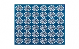
1. PCB wire welding pcb double-sided board
There is no need for any connectors, as long as the external connection points on the circuit board are directly welded to the components or other components outside the board with wires.
Attention should be paid to the interconnection and soldering of circuit boards :
(1) The pads of the welding wires should be as close as possible to the edge of the circuit board and arranged in a uniform size to facilitate welding and maintenance.
(2) In order to improve the mechanical strength of the wire connection and avoid pulling off the pad or the printed wire due to the wire being pulled, drilling holes should be drilled near the solder joints on the circuit board, so that the wire can pass from the welding surface of the printed board through the hole, and then insert the pad hole from the component surface for soldering.
(3) Arrange or bundle the wires neatly, and fix them with the board through wire clips or other fasteners to prevent the wires from being broken due to movement.
2. PCB cable welding
The two circuit boards are connected by a cable, which is reliable and less prone to connection errors, and the relative positions of the two circuit boards are not limited.
The printed boards are directly welded. This method is often used for the connection between two printed boards at an angle of 90 degrees. After the connection, it becomes an integral circuit board component.
Connector connection method
In more complex instruments and equipment, connectors are often used to connect. This "building block" structure not only ensures the quality of mass production of products, but also reduces the cost of the system, and provides convenience for debugging and maintenance. When the equipment fails, the maintenance personnel do not have to check the component level (that is, check the cause of the failure and trace the source to the specific components. This work takes a considerable amount of time), as long as it is necessary to determine which board is abnormal. It can be replaced immediately, troubleshooting in the shortest time, reducing downtime and improving equipment utilization. The replaced circuit board can be repaired in ample time, and can be used as a spare part after repair.
Flexible fpc soft board
1. PCB socket
In more complex instruments and equipment, this connection method is often used. This method is to make a printed plug from the edge of the circuit board, and the plug part is designed according to the size of the socket, the number of contacts, the distance between the contacts, and the position of the positioning hole, so that it matches the special circuit board socket.
When making the board, the plug part needs to be gold-plated to improve wear resistance and reduce contact resistance. This method is easy to assemble, has good interchangeability and good maintenance performance, and is suitable for standardized mass production. The disadvantage is that the cost of the printed board is increased, and the manufacturing precision and process requirements of the printed board are higher; the reliability is slightly poor, and the plug part is often oxidized and the contact is poor. In order to improve the reliability of external connection, the same lead wire is often led out in parallel through the contacts on the same side or both sides of the circuit board.
2. Standard pin connection
This method can be used for external connection of printed boards, especially in small instruments, pin connections are often used. The two printed boards are connected by standard pins, and the two printed boards are generally parallel or vertical, which is easy to achieve mass production.
Mob: 13570819121
Email: txspcbsc@163.com
Web : www.txspcb.cn
Add: Jinkang, No. 1 Shajing Road, Baoan District, Shenzhen
3rd Floor, Building 3, Industrial Park

SWEEP
 Online Service


 中文
中文 English